|
|
|
Engine Block
All engines produce power in the combustion chambers of the cylinders, and the design of the cylinder head is what determines how much power is generated. But in order to use the power generated from the combustion process, the pressure energy must be converted into a usable form. The pistons, connecting rods and crankshaft are what convert the energy into a useful form. None of these components in themselves can add power. In fact, the conversion process is actually quite inefficient, and a lot of power is wasted doing so. But what we can do is use them in a way that reduces the amount we lose. When the various components are moving, energy is being used to overcome friction. This occurs between the cylinder walls and the piston rings, between the piston and the gudgeon pins, the gudgeon pins and the connecting rods, the connecting rod bearings and the crank and the crank and the main bearings. All that lost energy is being converted to heat, which is then taken away by the coolant or oil, or radiated off the block directly. As well as all this, even more losses are being suffered. The oil pump, the water pump, the alternator, the camshafts, the valves, they all add to the losses. It doesn't stop there. When you accelerate an engine, some of the power being generated is used to accelerate the engine itself, rather than the car. So what can be done? It is obvious that reducing friction must help. The trouble is, there are not really very many ways to significantly reduce this on a road engine. Some companies sell additives that contain 'low friction' elements that are claimed to reduce the internal friction of an engine when added to oil. These do not offer any real advantage, and their value is debatable. It is considered that the use of a good quality oil is just as effective. Beyond this, only reducing the number of parts will reduce friction, and there is not really any way to do that on a production engine. Race engines employ various techniques that help, for instance using two thin piston rings where a production engine would use three wider ones, but this vastly increases the wear rate of the rings. Another technique is using cylinders with a bore to stroke ratio that optimises the area the rings sweep. This strikes a balance between a wider area and a faster speed. Friction increases with the square of speed, so if you double the speed, you get four times the friction three times the speed, nine times the friction etc. From this it can be seen that halving the area by halving the piston diameter means you double the length of the stroke; for the same rpm, the rings have to travel twice as far in the same time, doubling the speed, and quadrupling the friction... Not an easy thing to do, and impossible for a boxer engine in a production car. Unfortunately, there is practically nothing that can be done to reduce the inherent mechanical friction in a boxer engine other that making sure that everything is correctly built and dimensioned exactly the way the designer wanted the engine. This is called blueprinting. Correctly done, you can reduce losses a little, but the biggest advantage of blueprinting is reliability.
Flywheel modifications
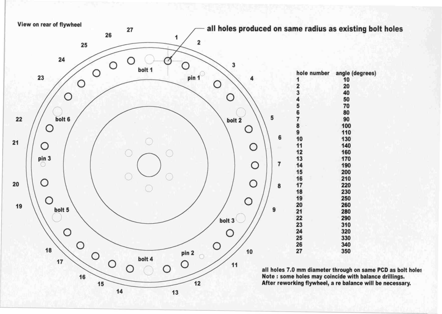
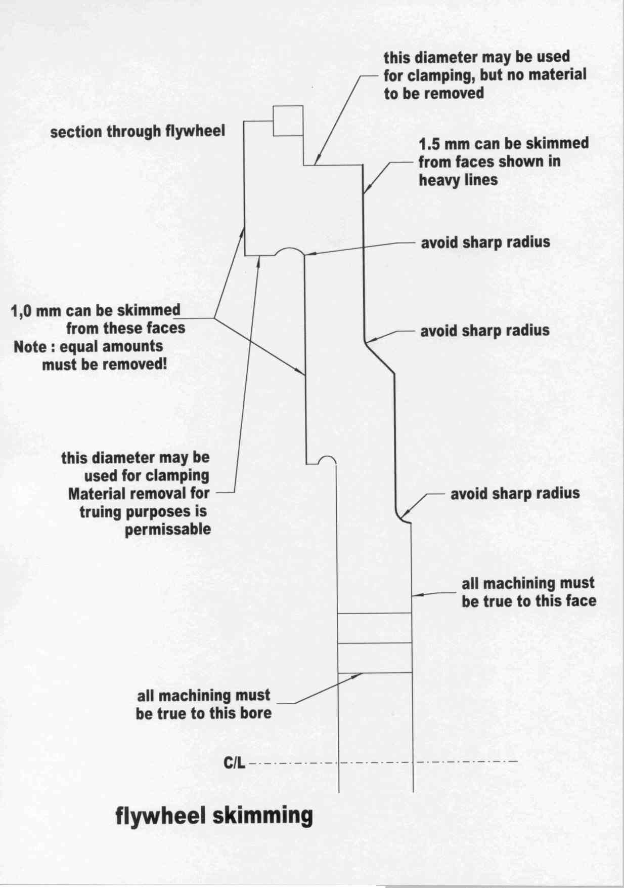
There are, however, some modification that can make a difference to how the engine behaves. If an object is heavy, for a given power it will be accelerated more slowly than a light object.take this one step further, and you can see that to accelerate the lighter object at the same rate as the heavier one, you need less power. Given this, if you make all the engine components lighter, they will absorb less power under acceleration. This allows the extra power that was not absorbed to be used to accelerate the rest of the car. Obviously, there is a limit to how light all the components can be made before they are unable to take the stresses and break. But there is also another more immediate limit. All engines use a mass to absorb the individual power pulses generated by the cylinders, so that a smooth delivery of power is obtained, plus it keeps the engine turning after the power stroke is finished long enough for it to complete another power stroke. The mass is the flywheel. It has to be of at least a certain mass in order for it to be able to complete that function, and the value will be different from engine to engine. The heavier the flywheel is, the greater the amount of energy it can store, and therefore the smoother the engine can run. In addition to this, as the car it is in is pulled away from standstill, the greater amount of energy stored in a bigger flywheel helps prevent the engine rpm dropping to much resulting in the engine bogging down or even stalling. The downside of this high mass is that the mass itself requires a lot of energy to accelerate. This robs power under acceleration, and it also makes the engine less responsive and free revving. To combat this, the flywheel can be lightened, but before embarking on this, a few pitfalls must be pointed out. The flywheel serves as a means of absorbing power, and as mentioned, aids when pulling away from a standstill. If too much material is removed, the idle will become erratic, and lots of revs will be needed to prevent stalling off the line. An increased idle rpm will help the first problem, but there is no easy solution to the latter. The flywheel also serves as a means of mounting the clutch assembly. Whatever the mods, the area of the flywheel that the clutch friction plate acts against must not be reduced, otherwise clutch slip may result. In addition, the attachment and seating of the clutch pressure plate must not be affected, otherwise failures can occur. If the friction plate face is skimmed, an equal amount must be removed from the pressure plate mounting area to maintain the correct pressure. Modified types of clutches are available, but they fall outside of the bounds of most road engines, so will not be dealt with here. The areas from which the material is removed from the flywheel must be limited is order to not make the flywheel too weak to withstand the stresses put upon it. Nor must it be removed from the locating diameters, the starter ring gear, and if fitted, the flywheel crank position sensor trigger teeth. The machining must not leave sharp internal radii so as to avoid stress concentrating features. Finally, the flywheel must be dynamically balanced complete with the other rotating parts. See notes on balancing later in this page. The Alfa Boxer flywheels are massively heavy, too heavy for their intended use, especially those fitted to injected engines. There are large amounts of material that can be safely removed without adversely affecting the idle or off the line properties. The following diagrams deal with the carburettor engine flywheels, but the principles can be readily read across to the later engines.
I cannot remember exactly how much weight these mods removed, but I do know that they are pretty conservative, and that more material can safely be removed. I used it on a carburettor 1500 engine, and there was no trace of a bad idle or poor stalling characteristics. As mentioned, flywheels fitted to injected engines and 16v engines are heavier still. If anyone has successfully modified a flywheel differently, I would be happy to include their technique here.
Pistons
The pistons fitted to boxer engines are good quality cast aluminium items, with a steel reinforcement band integrally cast in them. There is not much modification that can be done to them, and they are light enough that no effective lightening is necessary, or indeed possible. The only things that can be done other than making sure that they are not distorted or mis-dimensioned, is making sure that they are all the same weight, and applying a thermal barrier coating to the top face. When I produced my 1500, I was able to dress non critical areas of the pistons so that they all weighed within 1/2 a gramme of each other. I did this with the piston assembled, i.e. with the gudgeon pin, retention clips and rings fitted. Before you do start cutting material off the pistons, though, weigh all the individual components and write down the results. By carefully selecting the parts, you can achieve 90% of the balancing, and then you have less work to do after. Try and end up with one assembly heavier than the other three, rather than one lighter than the other three, otherwise you have to dress three pistons rather than one. The thermal barrier coating that I applied to my pistons is the same as was applied to the inlet valves (see 'Cylinder Head' section for details). The theory is that the less heat that is transferred to the piston crowns, the more heat is maintained doing work in the cylinder, and latterly the exhaust. t also means that as the piston crowns don't get as hot, the top ring land can be smaller, with the ring nearer the top. This reduces the dead area between the ring and the piston crown, aiding efficiency and emissions. The piston would also be more stable dimensionally due to the lower temperature gradient across it. Did I notice any difference? Well, as for the valves, it was installed along with other modifications, so there is no way of being able to determine how much is directly attributable to the coated pistons.
Connecting rods
The connecting rods of the Boxer engine can be lightened considerably, which, so long as they are still strong enough, give the same benefits as flywheel lightening, but without the disadvantages. The rods are forged steel items, and are pretty good quality material. They have a distinctive serrated 'fir tree' type joint between the rod and the big end cap, and the joint is at 45 degrees to the rod
Connecting rod mods The rods are 'I' section beam forged steel items, and are pretty good quality material. They have a distinctive serrated 'fir tree' type joint between the rod and the big end cap, and the joint is at 45 degrees to the rod. An important word of warning - Do not mix the big end caps up, as they are matched to and only fit one rod! Incorrect big end caps will mis align the shell bearings, and cause the rod to seize. The rods and big end caps leave the factory with balance pads cast on them, so that they can be roughly balanced to fairly wide production tolerances. In addition, there is plenty of excess metal from the forging process all the way down the beam of the rod. The excess material can be removed, and the beams polished. This results in the rods being lighter, and if the polishing is correctly done, stronger. By careful removal of the balance pads, the weights of the rods can be brought to a minimum, and the rods can also be matched weightwise to within very close tolerances. On my 1500, they were brought within 1/2 gramme of each other. The following diagram details what is involved, and if you refer to the photos of the rods from my 1500 in the photo page, it will help interpret the diagram. Crankshaft
The crankshaft on the boxer engines are fairly short, stiff items. As far as I know, they are all interchangeable, taking into account the additional strokes of the different sizes, so with the respective connecting rods and / or pistons, can be used to modify the bore and stroke to suit capacities and engine characteristics. Regrinding the crank to restore the finish of the crankpins and main journals is well recommended also Quite obviously, anyone wanting to maximise power will automatically try to get the largest displacement possible. In addition, by offset grinding the crank pins to the minimum diameter, and using the maximum undersize bearing shells, a (very) small increase in swept volume can be gained. On 'specials', the crankshafts are either replaced by custom made steel items, or are modified to take non-Alfa parts to change the stroke. Anyone with reasonable mechanical knowledge and patience would be able to do this, by investigating the parts bin of other engines. The only modifications available to the majority of us are going to be simple ones. Basically, we want to reduce crank losses. The crank loses power two ways, through mass, and through windage. The mass losses are well understood, as they are the same as the flywheel, but unfortunately the crank is a complicated component. A lot of the weight will be there not for mechanical strength, but for counter-balance weighting. By removal of this 'extra' material, the crank may not be able to damp out the vibrations arising from the pistons and rods, and the engine may shake itself to bits. With a good understanding of the stresses and vibrational forces involved, I am sure that it is possible to successfully modify the crank, but we are aficionados and amateur modifiers, so it's outside our realm. That leaves windage losses. These are the losses incurred by an awkwardly shaped lump of metal whizzing around. The air resistance as it rotates is one component, but the greater one is that of the oil entrainment and resistance. The common thought is that as the crankshaft rotates, it flings all the oil away by centrifugal action. Wrong, the crank actually acts like a whopping great egg beater, and the oil is sort of trapped by it. The crank is also acting to constantly dip and remove the crank webs in the oil. The energy required to churn all this machinery and fluids around is significant. One solution to part of it is to create a partial vacuum in the crank case. The means of achieving this is via a positive crankcase ventilation system, which uses exhaust pulses to pull the air out of the the crankcase. This uses an anti backfire valve to ensure that the exhaust doesn't blow up the crankcase. The oil entrainment is a little more tricky. By pulling the oil away from the crank, and ensuring it returns to the sump, you reduce this effect, and you can do this with a crank scraper. Basically, a crank scraper is a sheet metal 'comb', which sits as close to the crank as possible, and fitted around the lumps and bumps of the crank. It is designed so that it does not interfere with the moving parts, but as they pass close by, the oil hits the scraper and returns to the sump. By making this part of the sump pan, and combining it with sump pan baffles, the losses can be reduced, and the maximum level of oil is available for the pump to pick up. Reducing the oil level to the minimum level marked on the dipstick is also known to reduce losses by a couple of bhp due to reducing the oil windage. But the lowest oil level is more prone to oil surge under high 'G' loadings. By using a baffled sump and the oil scraper, the lowest oil level can be used safely. In addition, considering the shape of components is important. A flat faced lump of metal with square edges is always going to present more resistance when moved through viscous oil that one with a suitably blended streamlined shape. If you look at the crank, none of the edges are rounded off, in fact the crank counterbalance webs are anything but streamlined. The solution is to blend all the edges so that the crank is smoothed off. The amount of material removed by this is fairly minimal, so counter-balance is not a problem. You must rebalance the crank assembly afterwards though. Refer to the section on balancing.
Cam Wheels
Following on from reducing the rotating weight, though the cam wheels are relatively light, and rotate at half engine speed, any weight that can be removed will help. The difference in itself will be minor, but lots of small improvements add up. The wheels can be drilled with large holes in the webs, and material removed from under the toothed rim, as per the diagrams.
Cylinders, piston rings and bores
When refurbishing an engine, it is always worth checking the bores of the cylinders for wear, scoring, ovality, cracking, porosity etc. A modified engine puts extra strain on the cylinders, and if the bores or rings are worn, or there are problems with the block, they will quickly become evident. This not only wastes the effort you put in elsewhere, but could cause a destructive failure, and take the good work you did down with it. If nothing else, worn bores waste power through blow-by, they consume oil, and will not last long. The crankcase pressure that builds up because of blow-by forces oil into the cylinders and down the valve guides. Oil reduces the octane rating of the fuel, so detonation is more likely to occur. Mot emissions failures are more likely. Without a doubt, though, the best way is to fit new, oversize pistons and rings, and rebore your engine to suit them. The trouble is that it is expensive. The pistons and rings will set you back over 200 pounds, and then you have to rebore your engine. If you are going to all this trouble, you should skim the block faces to raise the compression ratio too (see below), and it would be a false economy to not re-grind the crank and fit new main, big-end and thrust bearings, and balance the whole assembly. Don't forget to replace the core plugs in the block. A full gasket set is going to be needed, and unless you want to do it all again in 2000 miles, you really need to fit a new oil pump and filter. Though they can be changed at a later date, you then will really have to see if the valve guides in the heads are ok etc. Once all this has been done, you will find yourself a lot lighter in the pocket department. When reboring, make sure that a good quality honed finish is obtained, and when you do this, the block must be as it would be if it were in use. That means that the main bearing caps must be in their correct positions and fully tightened, so that the block is pulled into the correct shape, and if possible a deck plate fitted to the cylinder head face to simulate the slight distortion that results from the head being bolted down. In theory, the front and rear crankcase covers should be fitted and the block heated to 90 degreed C, as this is what is actually seen in action, although it is doubtful that any but the most devout machine shops would go to that extent. This will ensure that the shape of the cylinders is round when the engine is running normally, at full temperature. Unfortunately, as metal heats, it expands, and different thicknesses will have temperature gradients through them, so they distort slightly. In addition, aluminium cylinder heads and crankcase end covers expand at a greater rate than the iron block, so there are stressed applied to the block. This all makes the perfectly round bores you produced when the block was cold and unstressed distort slightly, so the pistons are not running in a perfectly circular bore. Happily, the distortion is not so great as to seriously affect the boxer engine, but when reboring and honing, at least fit the main bearing caps as a precaution. Any other improvements above this are welcome but not essential. All this work, apart from the block skim, will do nothing to raise the power of the engine, and you will have spent quite a bit of money. The only consolation I can give is this; If you can do a lot of the work yourself, be patient, shop around, a fair quantity can be saved. However, there is another alternative. Although purists frown on it, a simple way of improving your engine is available, as long as the following conditions exist: the bores are not severely worn, with a step in the bore at any point; The bores are not scored There are no signs of cracking or porosity You are not wanting another 100,000 miles out of your engine without a rebuild By re-ringing the pistons, you can improve the sealing, and restore the bottom end relatively cheaply. You will have to check the pistons for the following: Ring grooves and side of pistons worn excessively Crown damage (sometimes visible as the top piston ring groove being too small) Badly distorted skirts If any of these conditions occur, source another piston. The rings fitted must be new ones, and the bores must be de-glazed, which basically is a fancy way of saying roughen up the surface. The reason for this is that the smooth polished bores are too smooth for the new rings. The rings and bores should wear together so that they match. This is the 'running in' process. If the bores are too smooth, the rings just ride over the top, and never bed in properly, allowing leakage. In addition, the rougher surface traps small quantities of oil, which aid the running in process, and reduce friction. Of course, should the bores be beyond re-ringing, the alternative is to over-bore a smaller engine block By re-ringing some pistons, I was able to make a cheap 1500 engine, using a 1500 engine and a 1300 block. I rebored the 1300 block to exactly match the 1500 pistons, and with new rings, rebuilt it. It worked perfectly. It follows that if you have a 1700 with worn bores, by boring out a 1500 block, you are able to achieve the same result. The only cautionary note is that you will have to be aware of the possibility of the water ways breaking through into the cylinder bore. Checking the wall thickness of the bores would be a good precaution if you can do it - some companies have ultra-sonic non-destructive testing equipment which can do this, quite cheaply and quickly. I have to say that you would be unlucky to find a 1500 block with thin walls, though, and 1500 engines are cheap. By measuring the crank journals, and inspecting them for wear, scoring etc., it is possible to buy the shell bearings to suit them, and re-fit without re-grinding. It is not ideal, but I have done it, and the engine runs perfectly ok. When doing this, make sure the oil pump is in good condition. Also, don't use cheap oil, use at least GTX or an equivalent. In this way, a cheapish engine can be built that will serve you for 20-30,000 miles ok. One of my 1500 engines built like this with the porting mods on the other pages (minus the ceramics) with the 95 bhp cams produced a true 100 bhp, and was still doing so when I sold it at 12,000 miles. To my knowledge it is still going ok. As second hand engines are so cheap, mixing and matching to find the best tolerance matches shouldn't be a problem.
Balancing the rotating assembly
A common myth is that balancing an engine gives extra power. It doesn't. If an engine is so badly balanced that correcting the imbalance gives more power, that engine was destined to a short life anyway. What balancing does do is make an engine smoother and more reliable. It makes the engine nicer to use, and encourages the driver to make the most of the rev range
Compression Ratio
I'm not going to bore anyone with in depth calculations, just trust me that up to a certain point, the higher the compression ration (CR), the more power you'll get. The reason that diesels have so much torque is due to the phenomenal compression ratios they use, like 22:1. It increases the brake mean effective pressure on the piston, which directly translates as torque. High CR's also bring out the best in aftermarket cams. As an additional benefit, economy will increase slightly. There is a limit to what we can use, though. Once above 11:1, detonation problems start occuring with petrol engines, due to the octane rating of the fuel. The compression ratio quoted by Alfa as what the boxer engines are buit with is 9.5:1, but in prectice, the engines are never built with that high a ratio due to production tolerances. That means that the power will be down. The 95bhp standard engines were commonly found to be less than 90bhp, due to low CR's and other products of a wide tolerance. For boxer engines, the practical limit seems to be around 10.5:1, or thereabouts. The only practical method of raising the CR is to skim the block faces to reduce the cylinder volume at TDC, as the heads have virtually no combustion chamber in them. You will have to calculate the exact amount to remove yourselves on a engine to engine basis, as you have to consider which heads and cams you will be using. For production 1300 and 1500 twin carburettor engines, 0.5mm can normally quite safely be removed from each face without fear of any problems. PLEASE DO SOME MEASUREMENTS BEFORE DOING THIS. If you have any doubts, talk to a garage mechanic, as they will be able to help you determine the safe amount.
Disclaimer I AM NOT RESPONSIBLE FOR ANY DAMAGE RESULTING FROM THE INFORMATION CONTAINED ABOVE.
|